
This article provides a practical and technical explanation of the topic, including real-world use cases and insights.
ESP32-C3 SuperMini Complete Guide: Pinout, Arduino IDE Setup, WiFi, Bluetooth, PWM, ADC and OLED
The ESP32-C3 SuperMini is a compact and low-cost IoT development board based on the Espressif ESP32-C3 chip. It combines a 32-bit RISC-V microcontroller, 2.4 GHz WiFi, Bluetooth Low Energy, GPIO pins, ADC inputs, UART, SPI and I2C interfaces in a very small form factor.
This tutorial explains the board specifications, pinout, external power supply, Arduino IDE configuration, LED test, WiFi scan, WiFi connection, hotspot mode, Bluetooth scan, BLE server, digital pins, PWM, analog input, serial communication and OLED I2C display connection.
Quick Overview
The ESP32-C3 SuperMini is suitable for IoT projects, sensor nodes, wearable prototypes, automation systems, web servers, wireless monitoring, OLED displays, Bluetooth Low Energy experiments and low-power applications. Its small size makes it easy to integrate into compact electronic projects.
In this guide, we use the Arduino IDE because it is simple, beginner-friendly and widely used. However, the same board can also be programmed using other development environments such as ESP-IDF or PlatformIO.
1. Product Introduction
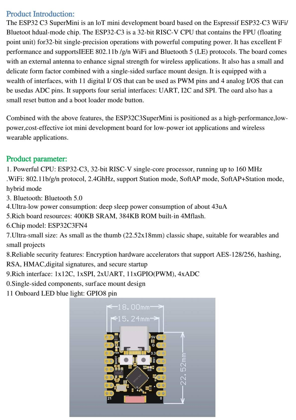
The ESP32-C3 SuperMini is an IoT mini development board based on the Espressif ESP32-C3 WiFi and Bluetooth Low Energy chip. The ESP32-C3 uses a 32-bit RISC-V single-core processor running up to 160 MHz and provides enough computing power for many connected embedded applications.
The board supports IEEE 802.11 b/g/n WiFi in the 2.4 GHz band and Bluetooth 5 Low Energy. It is designed for low-power IoT systems, wireless sensor nodes, wearable electronics and small automation projects.
Thanks to its small size and single-sided surface-mount design, the ESP32-C3 SuperMini is easy to place inside compact enclosures. It also includes a USB Type-C connector, BOOT button, RESET button, onboard LED and multiple GPIO pins for sensors and modules.
2. Product Parameters and Main Features
| Feature | Description |
|---|---|
| Chip | ESP32-C3, 32-bit RISC-V single-core microcontroller |
| CPU Frequency | Up to 160 MHz |
| Wireless | 2.4 GHz WiFi 802.11 b/g/n and Bluetooth 5 Low Energy |
| Memory | 400 KB SRAM, 384 KB ROM and commonly 4 MB flash on SuperMini boards |
| GPIO | Multiple digital GPIO pins, PWM support and analog inputs |
| Interfaces | UART, I2C and SPI |
| Security | Hardware acceleration for cryptographic functions such as AES, RSA, HMAC and secure boot features depending on configuration |
| Size | Approximately 22.52 mm × 18 mm, depending on board variant |
| Onboard LED | Blue LED usually connected to GPIO8 |
Important Note About Board Variants
ESP32-C3 SuperMini boards can exist in several low-cost variants. Pin labels, antenna layout, onboard LED behavior and voltage regulation may differ slightly between sellers. Always compare your board with its printed pin labels before wiring external modules.
3. ESP32-C3 SuperMini Pinout and Interfaces
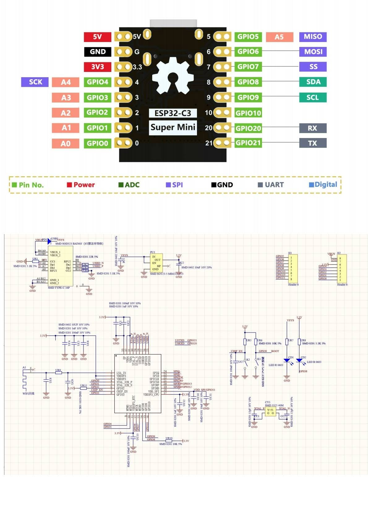
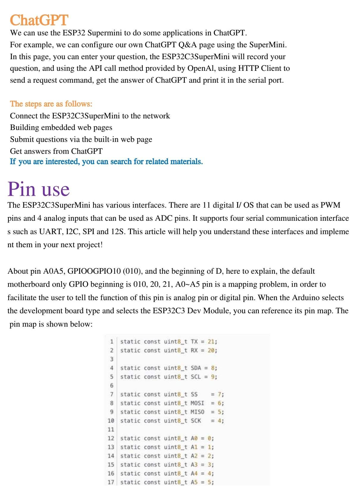
The ESP32-C3 SuperMini provides digital GPIO pins, ADC inputs, SPI, I2C and UART. The commonly used default mapping is shown below:
| Function | Common Pin | Notes |
|---|---|---|
| 5V | 5V | Power input/output depending on USB and board regulator design |
| 3.3V | 3V3 | Regulated 3.3 V output for low-current modules |
| GND | G | Common ground |
| ADC | A0 to A5 / GPIO0 to GPIO5 | Analog input pins |
| I2C SDA | GPIO8 | Default SDA in many Arduino mappings |
| I2C SCL | GPIO9 | Default SCL in many Arduino mappings |
| SPI SCK | GPIO4 | SPI clock |
| SPI MISO | GPIO5 | SPI MISO |
| SPI MOSI | GPIO6 | SPI MOSI |
| SPI SS | GPIO7 | SPI chip select |
| UART RX | GPIO20 | Hardware serial receive |
| UART TX | GPIO21 | Hardware serial transmit |
| Onboard LED | GPIO8 | Common on many ESP32-C3 SuperMini boards |
4. External Power Supply
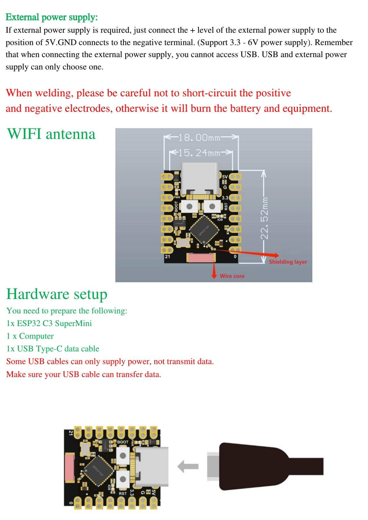
The ESP32-C3 SuperMini can be powered through the USB Type-C connector. Some board versions also allow external power input through the 5V and GND pins. Connect the positive terminal of the external supply to 5V and the negative terminal to GND.
Power Safety Warning
Do not connect USB power and an external power source at the same time unless your board documentation explicitly confirms that it is safe. Avoid short circuits between positive and negative terminals, because this can damage the board, battery, USB port or external equipment.
For battery-powered projects, use a stable 5 V power module or a safe 3.3 V regulated supply depending on the pin you use. Never feed more than the allowed voltage into the 3V3 pin.
5. Hardware Setup
To start programming the ESP32-C3 SuperMini, prepare the following components:
- 1 × ESP32-C3 SuperMini development board
- 1 × Computer with Windows, Linux or macOS
- 1 × USB Type-C data cable
- Optional: 0.96 inch I2C OLED display
- Optional: potentiometer for ADC testing
- Optional: USB-to-serial adapter for UART testing
USB Cable Tip
Some USB Type-C cables are power-only cables and cannot transmit data. If the board is powered but does not appear in the Arduino IDE port list, try another USB cable that supports data transfer.
6. Software Setup: Install ESP32-C3 in Arduino IDE
The easiest way to program the ESP32-C3 SuperMini is to use the Arduino IDE with the Espressif ESP32 board package.
Install Arduino IDE
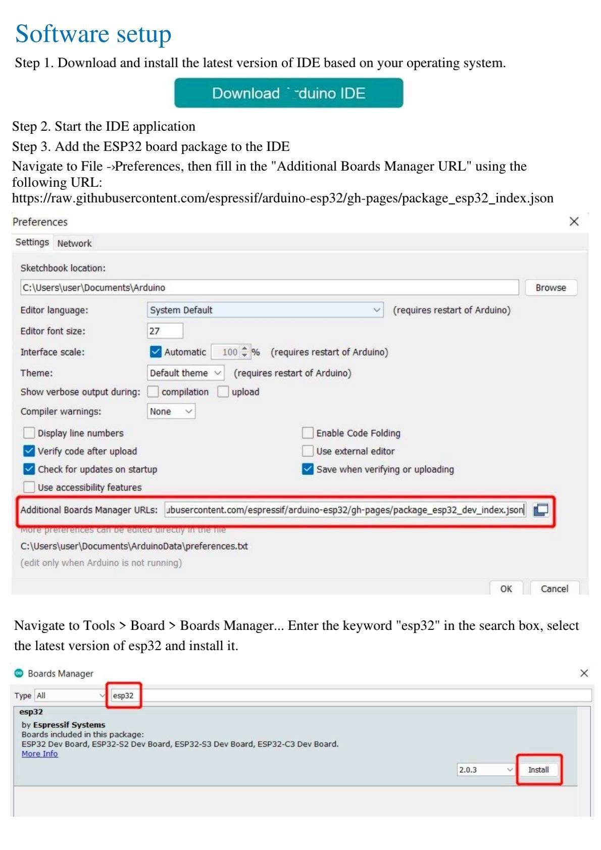
Download and install Arduino IDE 2 from the official Arduino website.
Add the ESP32 Board Manager URL
Open File → Preferences and add the following URL in Additional Boards Manager URLs:
https://espressif.github.io/arduino-esp32/package_esp32_index.jsonInstall ESP32 Boards
Go to Tools → Board → Boards Manager, search for esp32, select esp32 by Espressif Systems, then install it.
Select the Board
Go to Tools → Board → esp32 and select ESP32C3 Dev Module. On some systems the list is long, so scroll down carefully.
Select the Port
Connect the ESP32-C3 SuperMini to your computer, then select the correct serial port from Tools → Port. On Windows it is usually COM3 or higher.
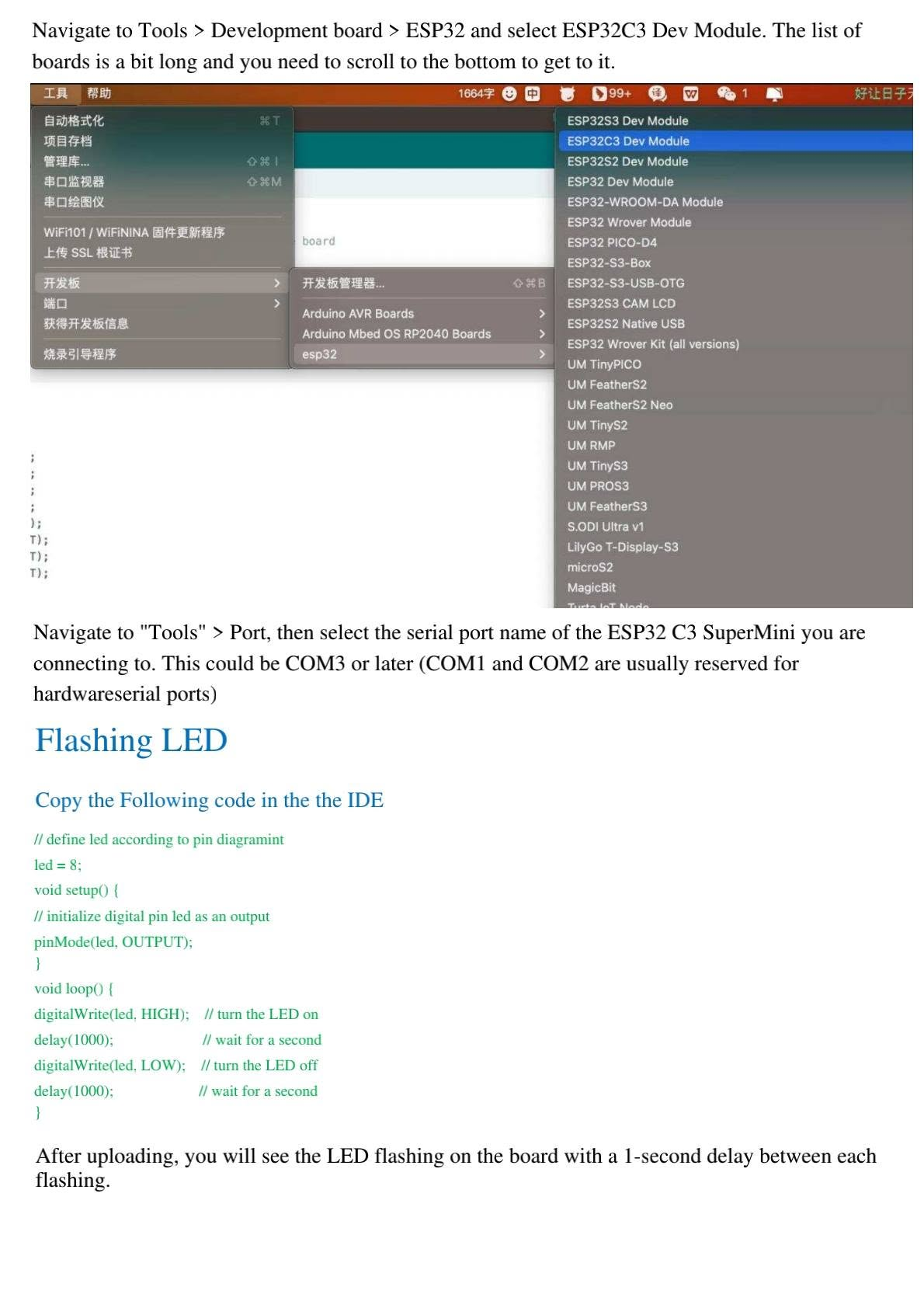
7. First Test: Flashing the Onboard LED
The first test is to blink the onboard LED. On many ESP32-C3 SuperMini boards, the blue onboard LED is connected to GPIO8.
const int led = 8;   // On-board blue LED on GPIO8

void setup() {
  pinMode(led, OUTPUT);
}

void loop() {
  digitalWrite(led, HIGH);  // LED ON
  delay(1000);
  digitalWrite(led, LOW);   // LED OFF
  delay(1000);
}
Upload the sketch. After uploading, the onboard LED should turn ON and OFF every second.
8. ESP32-C3 SuperMini WiFi Functions
The ESP32-C3 supports 2.4 GHz WiFi and can work in Station mode, Access Point mode and mixed modes. This makes it useful for IoT nodes, web servers, dashboards, sensor monitoring and local control systems.
8.1 Scan Available WiFi Networks
The following code scans nearby WiFi networks and prints the SSID, RSSI signal level and encryption indicator in the Serial Monitor.
#include <WiFi.h>

void setup() {
  Serial.begin(115200);
  delay(100);

  // Configure ESP32-C3 as WiFi station and disconnect from previous AP
  WiFi.mode(WIFI_STA);
  WiFi.disconnect();
  delay(100);

  Serial.println("Setup done");
}

void loop() {
  Serial.println("Scan start");

  int n = WiFi.scanNetworks();
  Serial.println("Scan done");

  if (n == 0) {
    Serial.println("No networks found");
  } else {
    Serial.print(n);
    Serial.println(" networks found");

    for (int i = 0; i < n; ++i) {
      Serial.print(i + 1);
      Serial.print(": ");
      Serial.print(WiFi.SSID(i));
      Serial.print(" (");
      Serial.print(WiFi.RSSI(i));
      Serial.print(")");
      Serial.println((WiFi.encryptionType(i) == WIFI_AUTH_OPEN) ? " " : " *");
      delay(10);
    }
  }

  Serial.println("");
  delay(5000);
}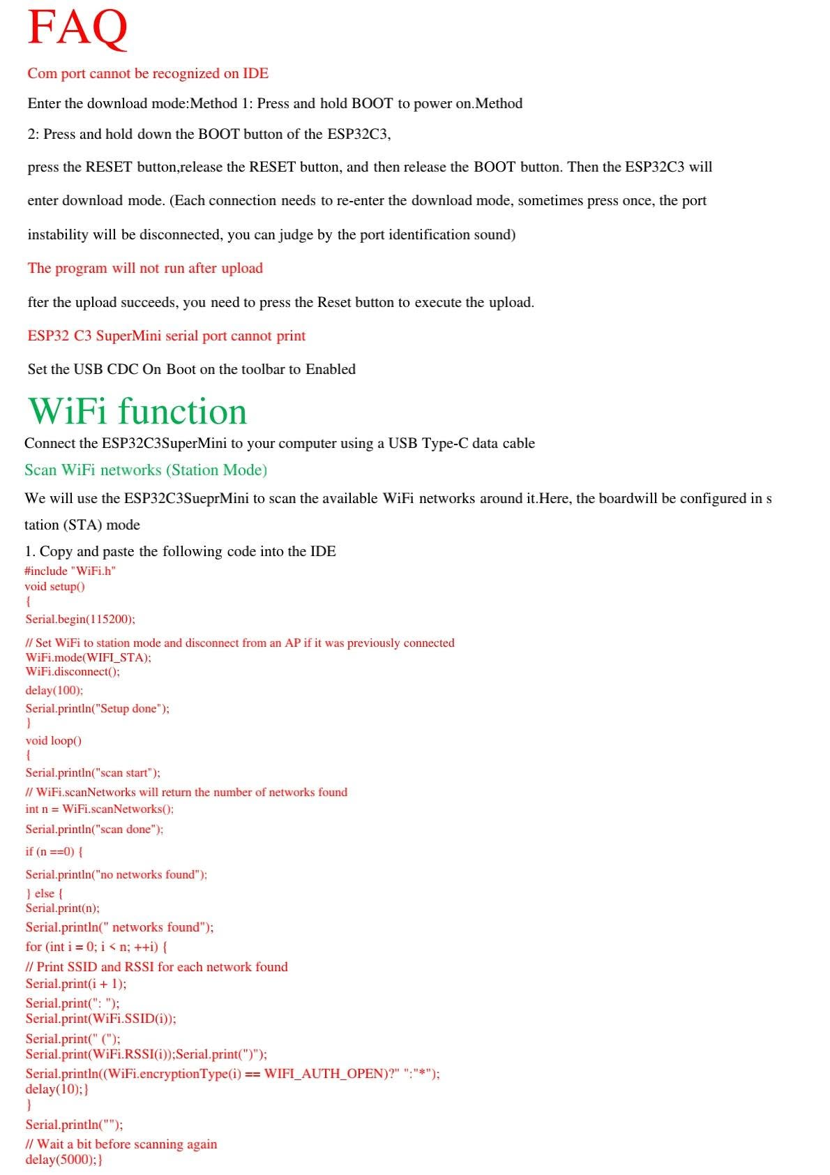
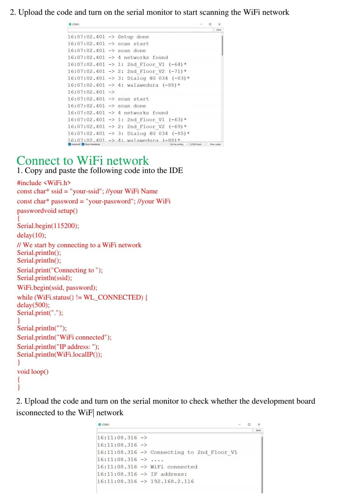
8.2 Connect to a WiFi Network
Replace YOUR_WIFI_NAME and YOUR_WIFI_PASSWORD with your own WiFi credentials. After successful connection, the board prints its local IP address.
#include <WiFi.h>
const char* ssid = "YOUR_WIFI_NAME";
const char* password = "YOUR_WIFI_PASSWORD";
void setup() {
Serial.begin(115200);
delay(100);
Serial.println();
Serial.print("Connecting to ");
Serial.println(ssid);
WiFi.begin(ssid, password);
while (WiFi.status() != WL_CONNECTED) {
delay(500);
Serial.print(".");
}
Serial.println();
Serial.println("WiFi connected");
Serial.print("IP address: ");
Serial.println(WiFi.localIP());
}
void loop() {
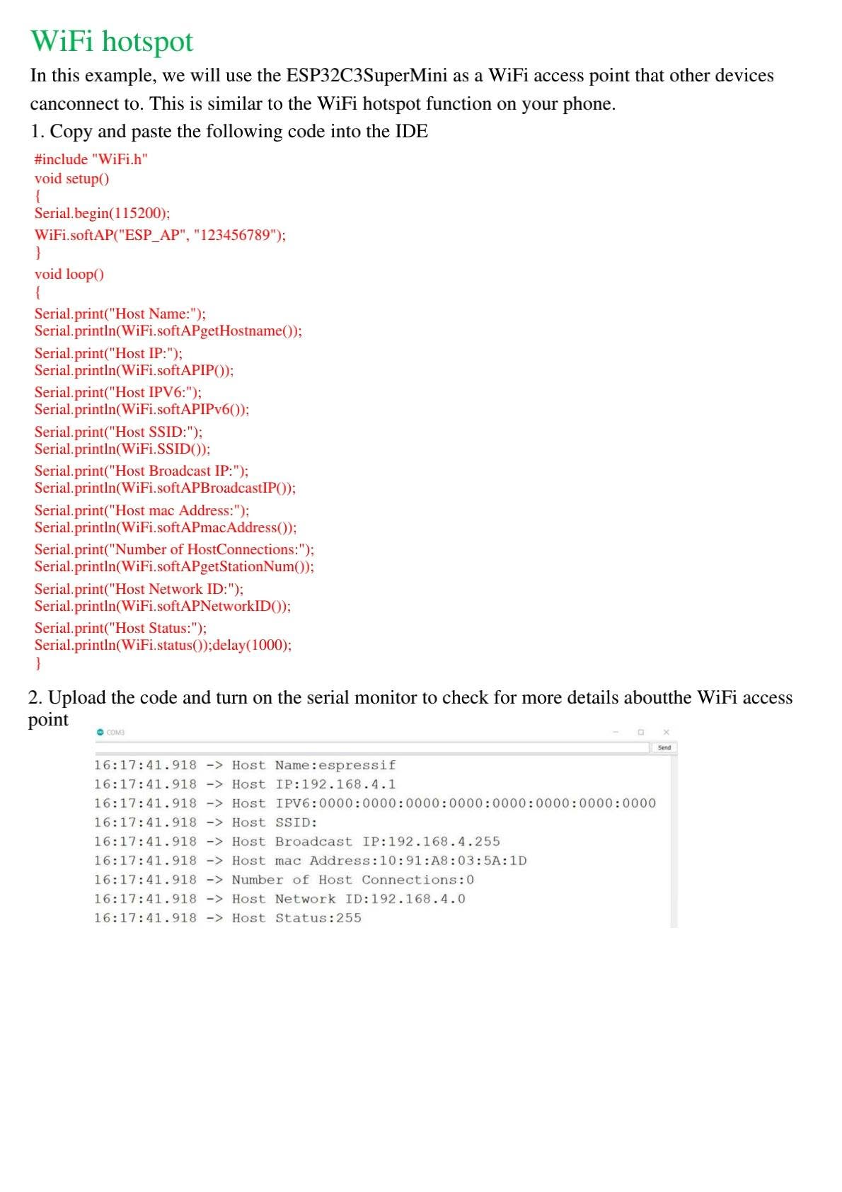
}8.3 Create a WiFi Hotspot / Access Point
The ESP32-C3 SuperMini can also create its own WiFi network. This is useful for configuration portals, local dashboards and offline IoT systems.
#include <WiFi.h>

const char* ap_ssid = "ESP_AP";
const char* ap_password = "123456789";  // Minimum 8 characters

void setup() {
  Serial.begin(115200);

  WiFi.softAP(ap_ssid, ap_password);

  Serial.print("Host Name: ");
  Serial.println(WiFi.softAPgetHostname());
  Serial.print("Host IP: ");
  Serial.println(WiFi.softAPIP());
  Serial.print("Host SSID: ");
  Serial.println(WiFi.SSID());
  Serial.print("Host MAC Address: ");
  Serial.println(WiFi.softAPmacAddress());
}

void loop() {
  Serial.print("Number of connected stations: ");
  Serial.println(WiFi.softAPgetStationNum());
  delay(1000);
}
9. Bluetooth Low Energy Functions
The ESP32-C3 supports Bluetooth Low Energy, which is useful for low-power communication with smartphones, sensors and nearby devices.
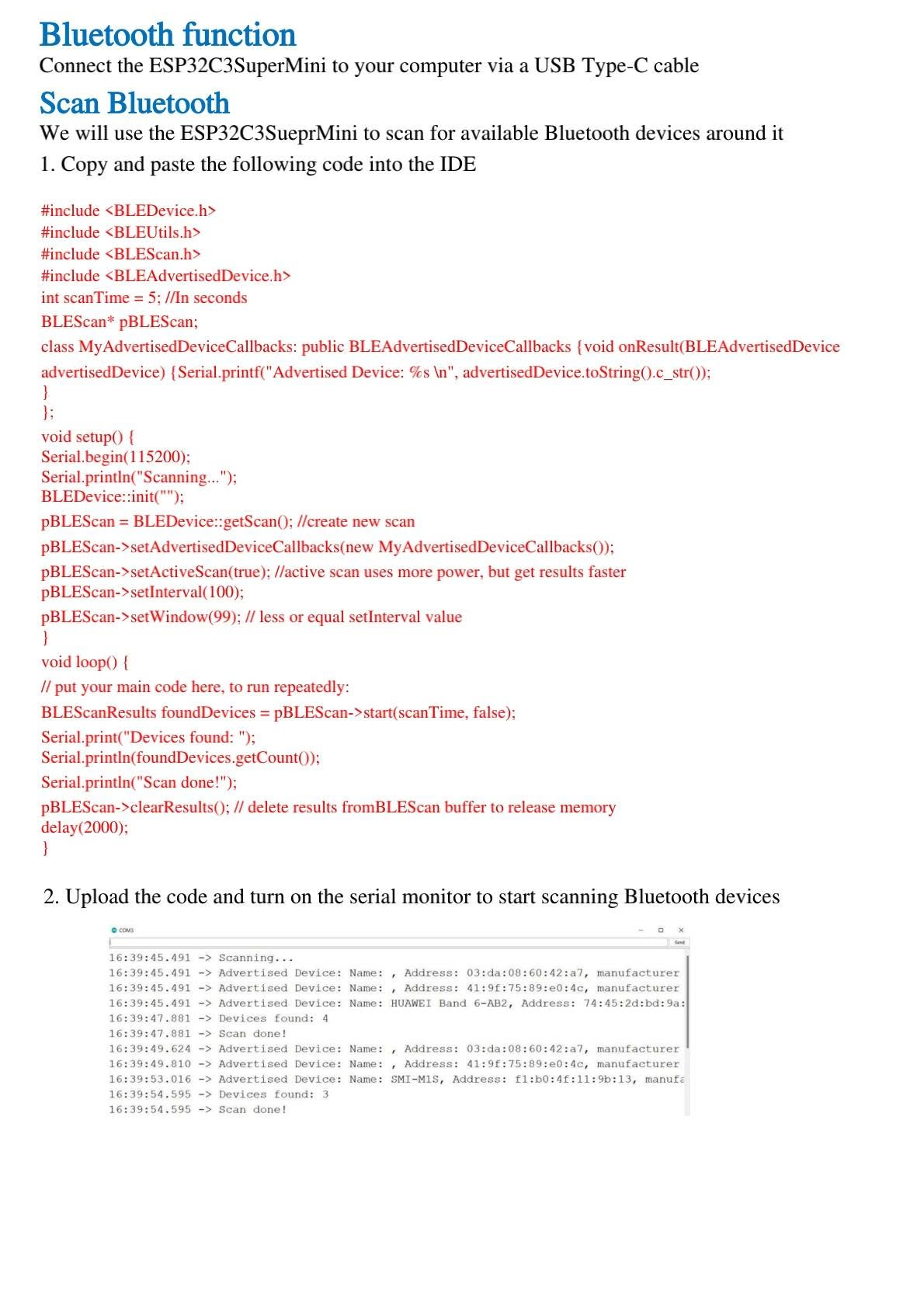
9.1 Scan Bluetooth Devices
This example scans nearby BLE devices and prints the results in the Serial Monitor.
#include <BLEDevice.h>
#include <BLEUtils.h>
#include <BLEScan.h>
#include <BLEAdvertisedDevice.h>

int scanTime = 5; // seconds
BLEScan* pBLEScan;

class MyAdvertisedDeviceCallbacks : public BLEAdvertisedDeviceCallbacks {
  void onResult(BLEAdvertisedDevice advertisedDevice) {
    Serial.printf("Advertised Device: %s\n", advertisedDevice.toString().c_str());
  }
};

void setup() {
  Serial.begin(115200);
  Serial.println("Scanning...");

  BLEDevice::init("");
  pBLEScan = BLEDevice::getScan();
  pBLEScan->setAdvertisedDeviceCallbacks(new MyAdvertisedDeviceCallbacks());
  pBLEScan->setActiveScan(true);
  pBLEScan->setInterval(100);
  pBLEScan->setWindow(99);
}

void loop() {
  BLEScanResults foundDevices = pBLEScan->start(scanTime, false);
  Serial.print("Devices found: ");
  Serial.println(foundDevices.getCount());
  Serial.println("Scan done!");
  pBLEScan->clearResults();
  delay(2000);
}
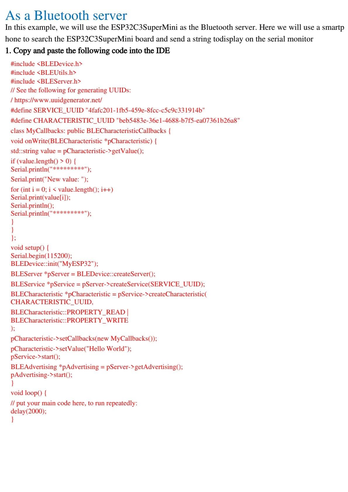
9.2 Use ESP32-C3 SuperMini as a Bluetooth Server
In this example, the ESP32-C3 SuperMini acts as a BLE server named MyESP32. A smartphone can connect to it using an application such as LightBlue and send a text string to the board.
#include <BLEDevice.h>
#include <BLEUtils.h>
#include <BLEServer.h>
#define SERVICE_UUID "4fafc201-1fb5-459e-8fcc-c5c9c331914b"
#define CHARACTERISTIC_UUID "beb5483e-36e1-4688-b7f5-ea07361b26a8"
class MyCallbacks : public BLECharacteristicCallbacks {
void onWrite(BLECharacteristic *pCharacteristic) {
std::string value = pCharacteristic->getValue();
if (value.length() > 0) {
Serial.println("**********");
Serial.print("New value: ");
for (int i = 0; i < value.length(); i++) {
Serial.print(value[i]);
}
Serial.println();
Serial.println("**********");
}
}
};
void setup() {
Serial.begin(115200);
BLEDevice::init("MyESP32");
BLEServer *pServer = BLEDevice::createServer();
BLEService *pService = pServer->createService(SERVICE_UUID);
BLECharacteristic *pCharacteristic = pService->createCharacteristic(
CHARACTERISTIC_UUID,
BLECharacteristic::PROPERTY_READ | BLECharacteristic::PROPERTY_WRITE
);
pCharacteristic->setCallbacks(new MyCallbacks());
pCharacteristic->setValue("Hello World");
pService->start();
BLEAdvertising *pAdvertising = pServer->getAdvertising();
pAdvertising->start();
Serial.println("BLE server started. Search for MyESP32.");
}
void loop() {
delay(2000);
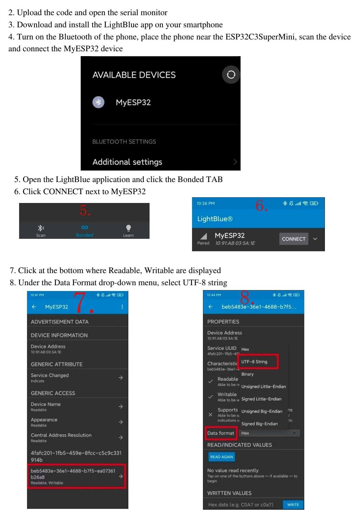
}9.3 Test with LightBlue App
- Upload the BLE server code to the ESP32-C3 SuperMini.
- Open the Serial Monitor at 115200 baud.
- Install and open the LightBlue app on your smartphone.
- Enable Bluetooth and search for the device named MyESP32.
- Connect to the device and open the writable characteristic.
- Select UTF-8 string format.
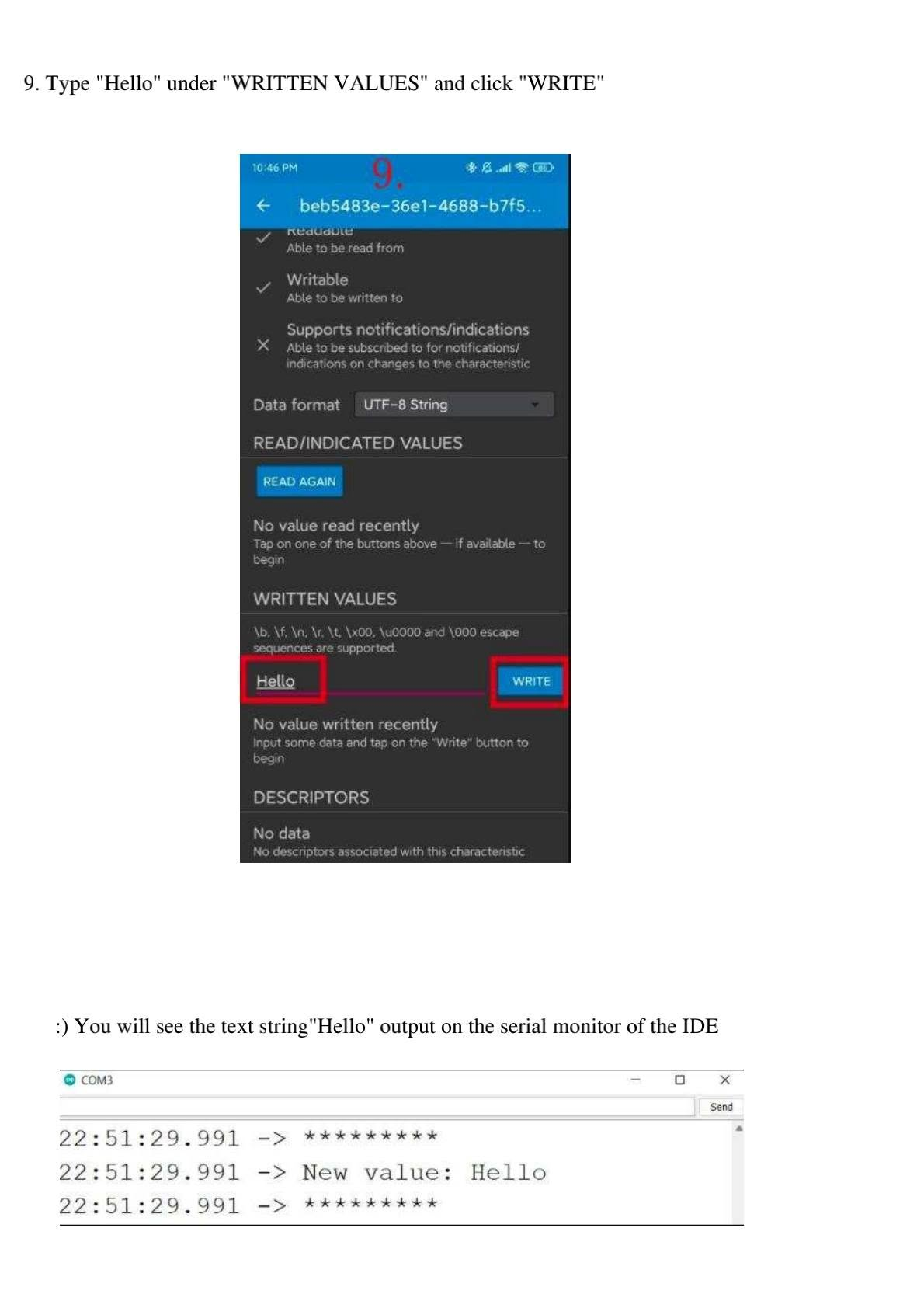
- Write the word Hello.
- The ESP32-C3 will print the received value in the Serial Monitor.
10. ChatGPT / AI Application Idea with ESP32-C3 SuperMini
The ESP32-C3 SuperMini can be used as part of an AI-connected IoT project. For example, you can build a small web page served by the board, let the user submit a question, send the request to a backend server, and display the answer returned by an AI service.
Important Security Note for API Keys
Do not hard-code private API keys directly inside firmware that can be shared, published or extracted from the device. A safer architecture is to send the ESP32 request to your own backend server, then the backend communicates with the AI API securely.
Suggested Architecture
- Connect the ESP32-C3 SuperMini to WiFi.
- Create a small embedded web page or send data through HTTP/MQTT.
- Forward the question to your secure backend server.
- The backend sends the request to the AI API.
- The response is sent back to the ESP32-C3 and displayed on Serial Monitor or OLED.
11. Digital Pins, PWM and Analog Input
The ESP32-C3 SuperMini includes digital pins that can be used for LEDs, relays, sensors and other modules. Some GPIO pins can also generate PWM signals, and several pins support analog input through the ADC.
11.1 Digital Pin Example
This is the same onboard LED blinking example using GPIO8:
const int led = 8;   // On-board blue LED on GPIO8

void setup() {
  pinMode(led, OUTPUT);
}

void loop() {
  digitalWrite(led, HIGH);  // LED ON
  delay(1000);
  digitalWrite(led, LOW);   // LED OFF
  delay(1000);
}
11.2 Digital PWM Example
This example gradually dims the onboard LED using PWM.
const int ledPin = 8;

void setup() {
  pinMode(ledPin, OUTPUT);
}

void loop() {
  for (int fadeValue = 0; fadeValue <= 255; fadeValue += 5) {
    analogWrite(ledPin, fadeValue);
    delay(30);
  }

  for (int fadeValue = 255; fadeValue >= 0; fadeValue -= 5) {
    analogWrite(ledPin, fadeValue);
    delay(30);
  }
}
11.3 Analog Pin Example
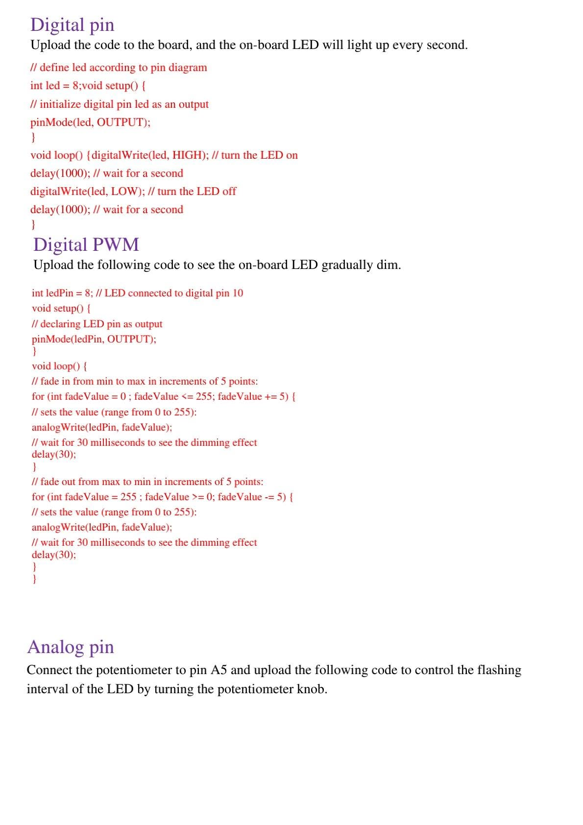
Connect a potentiometer output to an ADC pin such as A5. This code reads the analog value and changes the LED flashing speed depending on the potentiometer position.
const int sensorPin = A5;
const int ledPin = 8;

void setup() {
  pinMode(sensorPin, INPUT);
  pinMode(ledPin, OUTPUT);
}

void loop() {
  int sensorValue = analogRead(sensorPin);

  digitalWrite(ledPin, HIGH);
  delay(sensorValue);

  digitalWrite(ledPin, LOW);
  delay(sensorValue);
}
12. Serial Port and USB CDC
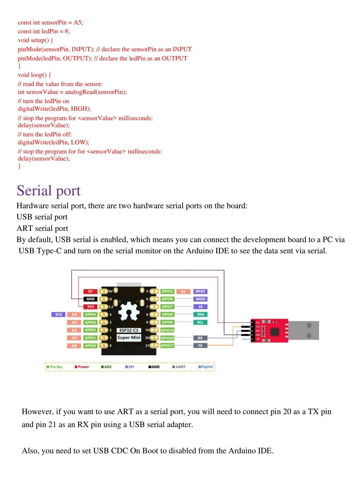
By default, the ESP32-C3 SuperMini communicates with your computer through USB serial. This is why you can open the Arduino IDE Serial Monitor and see messages printed with Serial.println().
The board also exposes hardware UART pins. A common mapping is GPIO20 as RX and GPIO21 as TX. When using a USB-to-serial adapter, connect adapter TX to ESP32 RX, adapter RX to ESP32 TX and GND to GND. Use only a 3.3 V logic serial adapter.
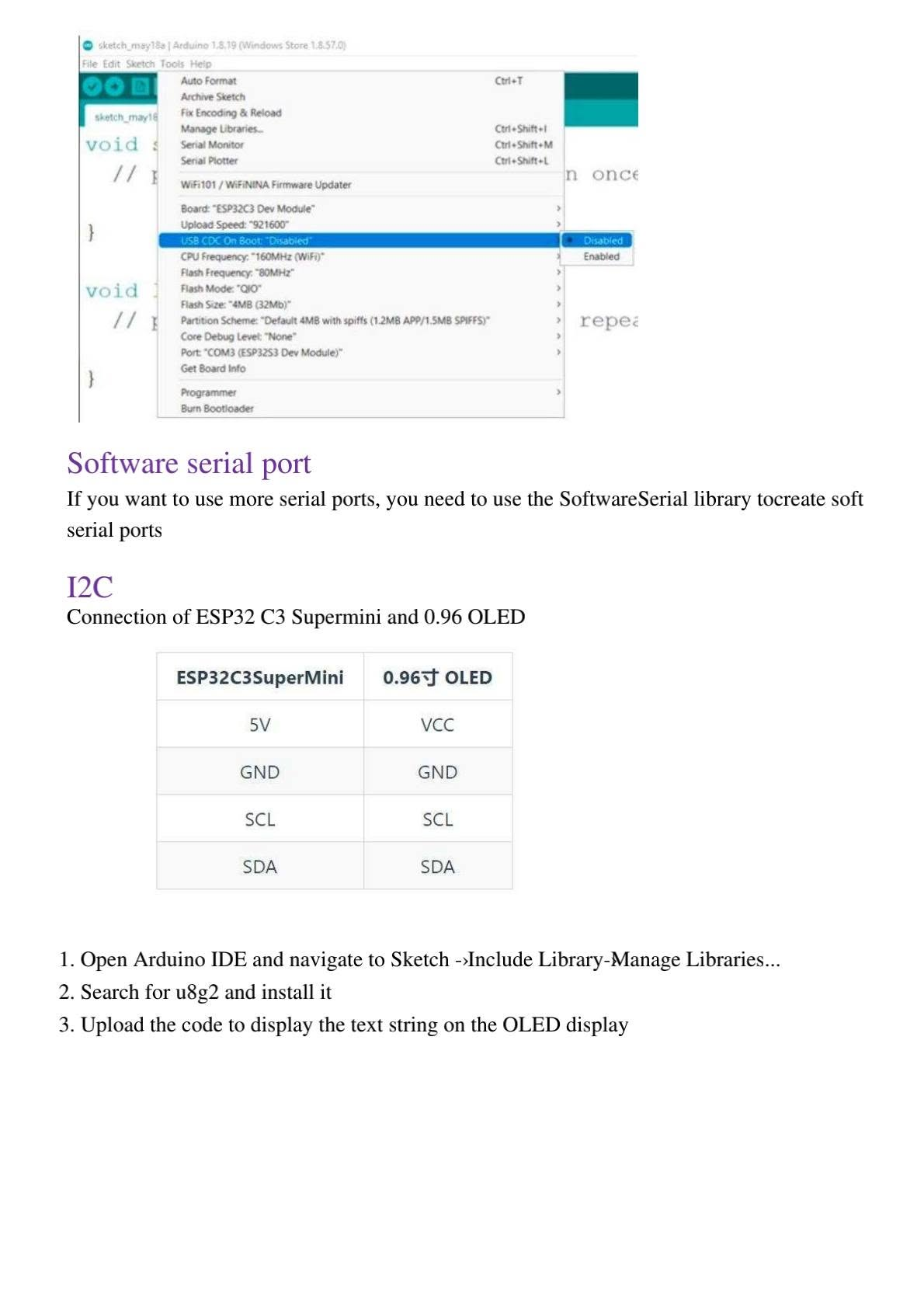
USB CDC On Boot
If the serial monitor does not print correctly, check the Arduino IDE option USB CDC On Boot. Some sketches require it enabled, while external UART tests may require different settings depending on your board package and connection method.
13. I2C OLED Display Connection
The ESP32-C3 SuperMini can easily control a 0.96 inch OLED display using the I2C interface. A common wiring is:
| ESP32-C3 SuperMini | 0.96 inch OLED |
|---|---|
| 5V or 3V3 | VCC, depending on your OLED module |
| GND | GND |
| GPIO9 / SCL | SCL |
| GPIO8 / SDA | SDA |
Install the U8g2 library from Sketch → Include Library → Manage Libraries, then upload this test code:
#include <Arduino.h>
#include <U8g2lib.h>
#include <Wire.h>

// ESP32-C3 SuperMini default I2C: SDA = GPIO8, SCL = GPIO9
U8G2_SSD1306_128X64_NONAME_F_HW_I2C u8g2(U8G2_R0, U8X8_PIN_NONE);

void setup() {
  Wire.begin(8, 9);
  u8g2.begin();
}

void loop() {
  u8g2.clearBuffer();
  u8g2.setFont(u8g2_font_ncenB08_tr);
  u8g2.drawStr(0, 20, "ESP32-C3 SuperMini");
  u8g2.drawStr(0, 40, "OLED I2C Test");
  u8g2.sendBuffer();
  delay(1000);
}
14. FAQ and Troubleshooting
The COM port is not recognized in Arduino IDE. What should I do?
Try another USB Type-C data cable, press RESET, hold BOOT while connecting the board, or enter download mode by holding BOOT, pressing RESET, releasing RESET and then releasing BOOT. Also check if the required USB driver is installed on your system.
The program uploads but does not run. What is the solution?
Press the RESET button after uploading. Also check the selected board, selected port and boot options in the Arduino IDE.
The serial monitor does not print anything.
Confirm the baud rate is set to 115200, check the correct COM port, verify USB CDC On Boot, and make sure the sketch contains Serial.begin(115200); inside setup().
Why does WiFi not connect?
The ESP32-C3 supports 2.4 GHz WiFi. Make sure your router is not using only 5 GHz, check SSID and password, and keep the board close to the router during testing.
Can the ESP32-C3 SuperMini be used for IoT projects?
Yes. It is suitable for IoT sensors, MQTT nodes, web servers, WiFi dashboards, BLE devices, OLED displays, remote monitoring and compact embedded systems.
SEO Settings for WordPress
Focus SEO Keyword
ESP32-C3 SuperMini Tutorial
SEO Title
ESP32-C3 SuperMini Tutorial: Arduino IDE Setup, Pinout, WiFi, Bluetooth and OLED
Slug
esp32-c3-supermini-arduino-ide-wifi-bluetooth-tutorial
Meta Description
Learn how to use the ESP32-C3 SuperMini with Arduino IDE. Full guide with pinout, external power, LED blink, WiFi scan, WiFi connection, hotspot, Bluetooth BLE, PWM, ADC, serial port and OLED I2C display.
Suggested Tags
ESP32-C3, ESP32-C3 SuperMini, Arduino IDE, ESP32 Tutorial, ESP32 WiFi, ESP32 Bluetooth, BLE, IoT, RISC-V, ESP32 Pinout, OLED I2C, PWM, ADC, Embedded Systems, Microcontroller
Suggested Categories
IoT, ESP32, Arduino, Embedded Systems, Electronics Tutorials
Image Alt Text Strategy
Use descriptive alt text such as “ESP32-C3 SuperMini pinout”, “ESP32-C3 Arduino IDE board manager setup”, “ESP32-C3 WiFi scan serial monitor” and “ESP32-C3 Bluetooth BLE server LightBlue app”.
Official References
- Arduino IDE official download and installation documentation.
- Espressif Arduino-ESP32 official installation documentation.
- Espressif ESP32-C3 official product and datasheet information.
- OpenAI API key safety best practices for projects that connect ESP32 devices to AI services.
Conclusion
This article highlights key aspects and practical applications of the discussed technology.
References
- IEEE Xplore Digital Library
- SpringerLink Research
- Google Scholar
Author: Mourad Elgorma
IoT & Networking Specialist
👉 Read more: Explore more ICT articles