
-
—
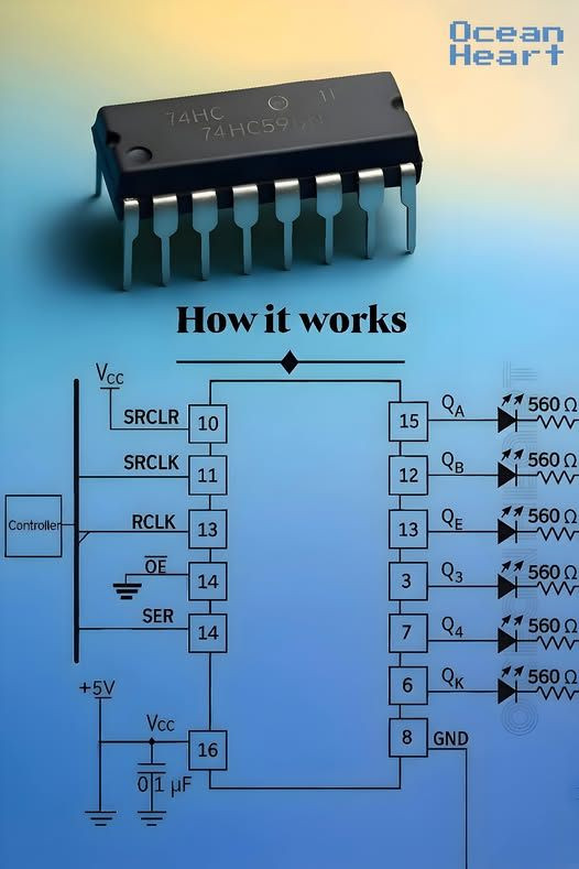
### 🔹 What is the 74HC595?
The **74HC595** is an **8-bit serial-in, parallel-out shift register with output latches**. It allows you to control multiple outputs (e.g., LEDs) using only a few microcontroller pins. This is very useful in microcontroller applications (like Arduino) when you want to expand the number of output pins.
—
### 🔹 Pin Functions
* **SER (14)**: Serial Data Input
Receives data bits (0 or 1) from the controller.* **SRCLK (11)**: Shift Register Clock
Each rising edge shifts the data from `SER` into the register.* **RCLK (12/13)**: Latch Clock (sometimes labeled as ST\_CP)
Transfers the shifted data from the internal register to the output latches, making the outputs (`Q0–Q7`) update.* **OE (13/14)**: Output Enable (active LOW)
Controls whether outputs are active. When pulled LOW, outputs are enabled; when HIGH, outputs are in high-impedance state.* **SRCLR (10)**: Shift Register Clear (active LOW)
Clears all data in the shift register when LOW.* **Q0–Q7 (15, 1, 2, 3, 4, 5, 6, 7)**: Parallel Outputs
These pins drive the external components (LEDs, displays, etc.). In the schematic, each output goes through a **560 Ω resistor** to an LED.* **Vcc (16)**: Power Supply (+5V).
* **GND (8)**: Ground.
* **Capacitor (0.1 µF)**: Decoupling capacitor between Vcc and GND for noise filtering.
—
### 🔹 How It Works
1. **Load Data (Serial Input):**
The controller sends a sequence of bits (0s and 1s) into the `SER` pin, one bit at a time, synchronized with `SRCLK`.2. **Shift Register Movement:**
Each clock pulse on `SRCLK` shifts the bits through the register. The register temporarily holds the 8-bit data.3. **Latch to Outputs:**
When the controller pulses `RCLK`, the data is copied from the shift register to the output latches (`Q0–Q7`).
This prevents the outputs from changing while new data is being shifted in.4. **Control Outputs:**
* `OE` enables or disables the outputs.
* `SRCLR` clears all data if needed.5. **Driving LEDs:**
Each `Q` pin is connected through a resistor to an LED. The resistor limits current (560 Ω in this example). When a `Q` output is HIGH, the corresponding LED turns ON.—
### 🔹 Applications
* Driving **LEDs** or **7-segment displays**.
* Expanding output pins on microcontrollers.
* Controlling relays, motors, or other digital devices in parallel.—
✅ In summary:
The **74HC595** takes **serial data from a microcontroller** and outputs it in **parallel** to drive multiple devices. It uses only 3 main control pins (SER, SRCLK, RCLK), which makes it very efficient for expanding outputs.—
Would you like me to also make a **step-by-step Arduino example code** showing how to light up LEDs using this exact circuit?
![]()


